
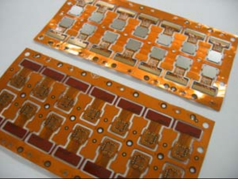
FPC Assembly (Flexible Printed Circuit Assembly), referred to as FPCA, means components soldering or Assembly of FPC boards.
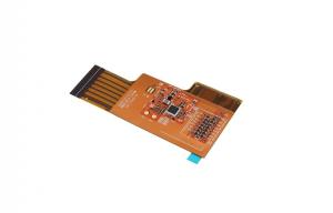
The miniaturization of electronic products is an inevitable development trend. Due to the space for assembly, SMD of a considerable number of consumer products are mounted on FPC to complete the assembly of the whole product. FPCA PCB as a semi-finished product, not FPC bare board, customers can directly install it and use it on the whole finished product.
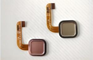
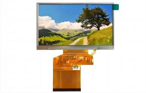
FPCA has been widely used in calculators, mobile phones, digital cameras, digital cameras and other digital products. Surface mount of SMD on FPC has become one of the development trends of SMT technology.
If you are looking for a reliable FPC Assembly partner in China, please don’t hesitate to contact us.
Several solutions to mount SMD on FPC
According to the requirements of mounting accuracy and different types and quantities of components, currently commonly used schemes are as follows:
Plan A: Simple mounting on a single FPC
1. Scope of application
- Component types: Mainly SMD assembly such as resistance and capacitance.
- Number of components: The number of components to be mounted on each FPC is small, usually only a few components.
- Mounting accuracy: The requirements for mounting accuracy are not high (only SMD components).
- FPC features: Small area.
- Batch quantity: Generally, it is measured in ten thousand pieces.
2. Manufacturing process
- Solder paste printing:
FPC is positioned on the special supporting plate for printing by its appearance, and is generally printed by A small semi-automatic special printing machine. Limited by conditions, we can also use manual printing, but the printing quality is not stable, the effect is worse than semi-automatic printing.
- Mounting:
Generally, manual mounting can be used. Some components with slightly higher position requirements can also be installed by manual Placement machine.
- Welding:
Generally, reflow welding process is adopted. Special equipment can also be used for spot welding under special circumstances. If manual welding, quality is difficult to control.
Plan B: Multi-piece mounting
Multi-piece mounting: Multi-piece FPC is positioned on the supporting plate by positioning template, and fixed on the supporting plate throughout the whole process for SMT mounting.
Application scope:
- Type of components:
Generally, the volume of chip components is greater than 0603, and the pin spacing is greater than or equal to 0.65 QFQ and other components are acceptable.
- Number of components:
From a few to a dozen components on each FPC.
- Mounting accuracy:
The mounting accuracy is medium.
- FPC characteristics:
The area is slightly large, there is no component in the appropriate area, each FPC has two MARK marks for optical positioning and more than two positioning holes.
There are many differences between FPC surface SMT process requirements and traditional RIGID PCB SMT solution. In order to do a good job in FPC SMT process, the most important thing is positioning.
Because the hardness of FPC board is not enough, flexible, if special supporting plate is not used, fixation and transmission cannot be completed, and basic SMT processes such as printing, SMT and furnace passing cannot be completed. The following details the key points of FPC pretreatment, fixation, printing, SMT, reflow welding, testing, inspection and board separation in FPC SMT production.
Manufacturing of special supporting plate
According to the CAD file of PCB, the hole positioning data of FPC PCB is read to manufacture the high-precision FPC PCB positioning template and special supporting plate, so that the diameter of the positioning pin on the positioning template matches the positioning hole on the supporting plate and the aperture of the positioning hole on the FPC PCB.
Many FPC PCB are not of the same thickness due to protecting part of the circuit or design reasons. Some parts are thicker and some are thinner, and some have reinforced metal plates. Therefore, the joint between the supporting plate and FPC PCB needs to be processed, polished and grooves dug according to the actual situation. The function is to ensure that the FPC is flat during printing and mounting. The material of the supporting plate should be light, high strength, less heat absorption, fast heat dissipation, and small warpage deformation after multiple thermal shocks. Commonly used supporting plate materials include synthetic stone, aluminum plate, silica gel plate, special high-temperature resistant magnetized steel plate, etc.
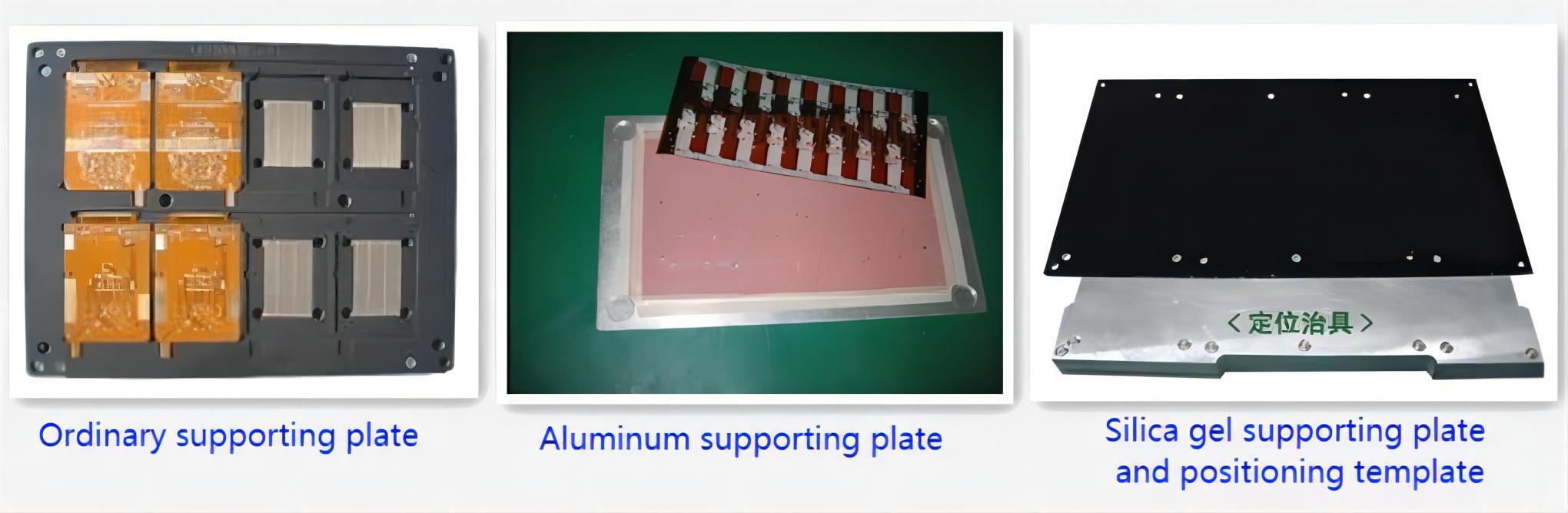
1. Ordinary supporting plate
Ordinary supporting plate is convenient for design and quick for proofing. Common supporting plate materials commonly used are engineering plastics (synthetic stone), aluminum plate, etc. Engineering plastic supporting plate has a life span of 3000-7000 times. It is easy to operate, stable, not easy to absorb heat, not hot to handle, and its price is more than 5 times that of aluminum plate.
Aluminum supporting plate absorbs heat quickly, has no temperature difference between inside and outside, and can be easily repaired for deformation. It is cheap and has a long life. The main disadvantage is that it is hot, so it needs to use heat insulation gloves to take and send it.
2. Silica gel supporting plate
The material is self-adhesive, FPC PCB is directly attached to it without adhesive tape, and it is easy to remove, no residual glue, and high temperature resistance. The silica gel supporting plate adopts a chemical process in the use process. The silica gel material will be aged and viscous in the use process, and the viscosity will also decrease when it is not cleaned during use. The service life is short, up to 1000-2000 times, and the price is relatively high.
3. Magnetic fixture
Special high temperature resistant (350℃) steel sheet to strengthen magnetization treatment, to ensure "permanent magnet" in reflow welding process, good elasticity, good flatness, No deformation at high temperature.
Because the steel sheet treated with enhanced magnetization has pressed the surface of FPC flat, FPC can avoid being blown up by reflow welding wind during reflow welding, so as to ensure stable welding quality and improve the qualified rate of FPCA finished products. As long as not man-made damage and accident damage can be used permanently, long life. The magnetic fixture also provides thermal protection to the FPC without any damage to the FPC when removing the plate. But the magnetic fixture design is complex, the unit price is high, and the cost advantage is achieved in mass production.
FPC Assembly Production Process
We take Ordinary supporting plate as an example to detail the SMT key points of FPC PCB. When silica gel supporting plate or magnetic fixture is used, the fixation of FPC is much more convenient without the use of adhesive tape, while the technological key points of printing, SMT and welding are the same.
1. The fixing method of FPC PCB
Before performing SMT, the FPC PCB needs to be precisely fixed to the supporting plate first. In particular, it should be noted that the storage time between fixing FPC PCB on the supporting plate, and then printing, mounting and welding should be as short as possible.
Supporting plate is available in two types: with or without a positioning pin. The supporting plate without positioning pin should be used with the positioning template with positioning pin. First, cover the supporting plate on the positioning pin of the template, so that the positioning pin is exposed through the positioning hole of the supporting plate, and cover the FPC on the exposed positioning pin one by one. The supporting plate was then fixed with adhesive tape and separated from the FPC positioning template for printing, pasting and welding. Several spring positioning pins about 1.5mm long have been fixed on the supporting plate with positioning pins. FPC can be directly covered on the spring positioning pins of the supporting plate one by one, and then fixed with adhesive tape. In the printing process, the spring positioning pin can be completely pressed into the supporting plate by the steel mesh without affecting the printing effect.
First cover the supporting plate on the positioning pin of the template, so that the positioning pin is exposed through the positioning hole of the supporting plate. Then cover the FPC piece by piece on the exposed positioning pin, and fix it with adhesive tape. Then separate the supporting plate from the FPC PCB positioning template. It is then printed, pasted and welded.
Method One (single-side tape fixation)
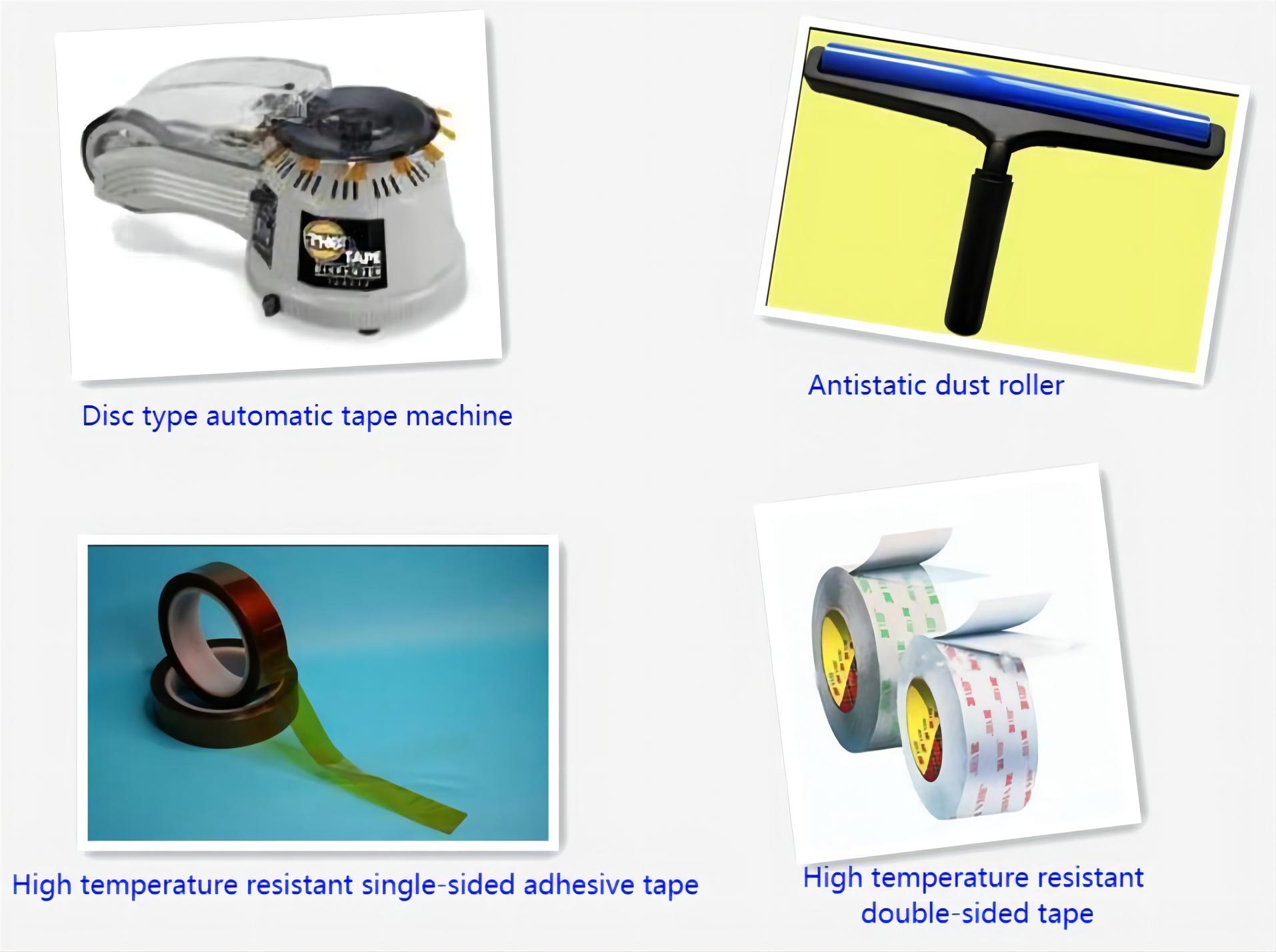
The four sides of FPC should be fixed on the supporting plate with thin high-temperature resistant single-sided adhesive tape to prevent the FPC from deviation and buckling. The viscosity of the adhesive tape should be moderate, and it must be easy to peel off after reflow welding, and there is no residual adhesive agent on the FPC. If the use of automatic tape machine, can quickly cut the length of the same tape, can significantly improve efficiency, cost saving, avoid waste.
Method Two (double-sided tape fixation)
High temperature resistant double-sided adhesive tape is first pasted on the supporting plate with the same effect as silica gel supporting plate, and then FPC PCB is pasted on the supporting plate. Special attention should be paid to the viscosity of the adhesive tape not being too high, otherwise, it is easy to cause THE TEAR of FPC when it is peeled off after reflow welding. After repeatedly going through the furnace, the viscosity of the double-sided tape will gradually become low, and the viscosity is so low that FPC cannot be reliably fixed that it must be replaced immediately.
This station is the key station to prevent FPC smudging, so it needs to wear finger sleeves. Before reusing the supporting plate, it should be cleaned properly, which can be cleaned with non-woven cloth dipped in cleaning agent, or anti-static dust roller can be used to remove dust, tin beads and other foreign matters on the surface. Do not use too much force when removing FPC. FPC is fragile and easy to produce creases and fractures.
2. Solder paste printing of FPC PCB
Because the supporting plate is loaded with FPC PCB, the high temperature resistant adhesive tape used for positioning on FPC PCB makes its plane inconsistent. So the printing surface of FPC PCB can not be as flat as PCB and the thickness of the same hardness, so it is not suitable to use metal scraper, and should use the hardness of 80-90 degrees of polyurethane scraper.
3. FPC PCB SMT
According to the characteristics of the product, the number of components and the efficiency of the SMT, medium and high speed SMT machine can be used for mounting. Since there is an optical Mark for positioning on each FPC PCB, SMD mounting on FPC PCB is not much different from that on PCB. It should be noted that although FPC PCB is fixed on the board, its surface can not be as flat as PCB hard board. There will certainly be local gaps between FPC PCB and the board. Therefore, the drop height and blowing pressure of the nozzle need to be set accurately, and the moving speed of the nozzle needs to be reduced.
4. Reflow welding of FPC PCB
Mandatory hot air convection infrared reflow furnace should be used so that the temperature on the FPC PCB can change more evenly and reduce the occurrence of bad welding. If it is the use of single-sided tape, because only the four sides of the FPC can be fixed, the middle part due to deformation in the hot air state, the pad is easy to form tilt, tin melt (high temperature
Under the liquid tin) will flow and produce empty welding, welding, tin beads, so that the process defect rate is higher.
5. FPC inspection, Testing and Splitting Board
As the supporting plate absorbs heat in the furnace, especially the aluminum supporting plate, the temperature is relatively high when it comes out of the oven, so it is better to add a forced cooling fan at the oven mouth to help rapid cooling. When taking the completed welded FPC from the supporting plate, the force should be even, and brute force should not be used to prevent the FPC from being torn or creased.
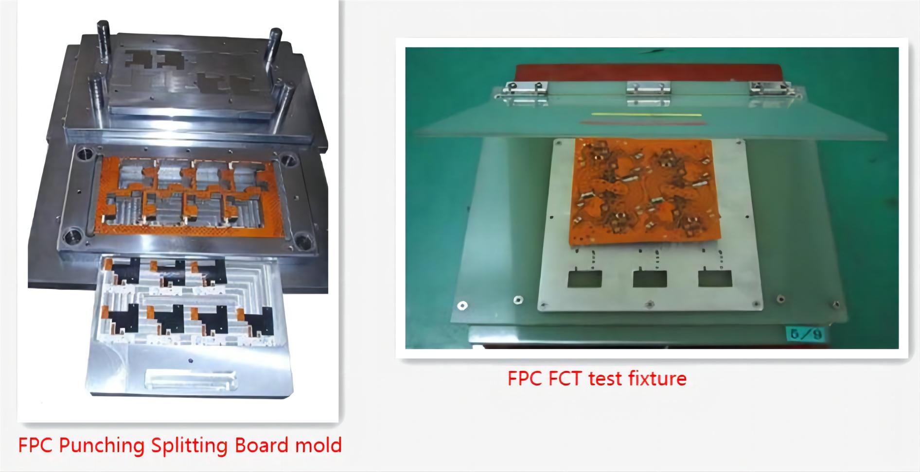
The removed FPC is placed under a magnifying glass of more than 5 times for visual inspection, focusing on the surface residual glue, discoloration, gold fingers with tin, tin beads, IC pin empty welding and welding. FPC is generally not suitable for AOI inspection because the surface of FPC may not be very smooth, resulting in a high misjudgment rate of AOI. However, FPC can complete ICT and FCT tests with the help of special test jig.
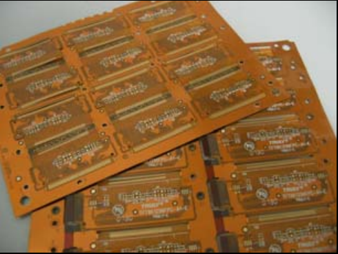
Since FPC is mainly composed of multiple single PCS in the form of Array splicing, Splitting PCB Board should be made before TESTING ICT and FCT. Although knives, scissors and other tools can also be used to complete the operation of Splitting PCB Board. However, the operation efficiency and quality are low and the scrap rate is high. For mass production of irregular FPC, it is suggested to make special FPC punching Splitting Board molds for stamping and Splitting, which can greatly improve the working efficiency. Meanwhile, the edges of FPC are neat and beautiful, and the internal stress generated during stamping and cutting plate is low, which can effectively avoid solder joint tin cracking.
One of the key points of SMD mounting on FPC is the fixation of FPC. Firstly, the quality of fixation directly affects the quality of mounting.
The next is solder paste selection, printing and reflow soldering. In the case of good FPC fixation, it can be said that more than 70% of the defects are caused by improper process parameter setting.
Therefore, the process parameters should be determined according to the differences of FPC, SMD components, thermal absorption of supporting plate, characteristics of solder paste selected, and characteristics of equipment parameters. Moreover, the production process should be controlled by dynamic control, abnormal situations should be found in time, correct judgment should be made, and necessary measures should be taken. In order to control SMT production defect rate within 10-50 PPM.